
Page 179 - System on Package_ Miniaturization of the Entire System
P. 179
154 Cha pte r F o u r
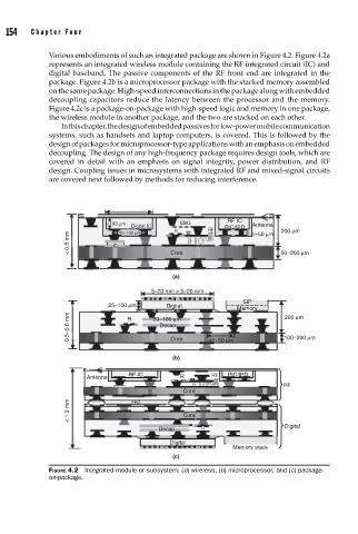
Various embodiments of such an integrated package are shown in Figure 4.2. Figure 4.2a
represents an integrated wireless module containing the RF integrated circuit (IC) and
digital baseband. The passive components of the RF front end are integrated in the
package. Figure 4.2b is a microprocessor package with the stacked memory assembled
on the same package. High-speed interconnections in the package along with embedded
decoupling capacitors reduce the latency between the processor and the memory.
Figure 4.2c is a package-on-package with high-speed logic and memory in one package,
the wireless module in another package, and the two are stacked on each other.
In this chapter, the design of embedded passives for low-power mobile communication
systems, such as handsets and laptop computers, is covered. This is followed by the
design of packages for microprocessor-type applications with an emphasis on embedded
decoupling. The design of any high-frequency package requires design tools, which are
covered in detail with an emphasis on signal integrity, power distribution, and RF
design. Coupling issues in microsystems with integrated RF and mixed-signal circuits
are covered next followed by methods for reducing interference.
RF IC
<100 μm EBG Antenna
Digital IC PIC/IPD
R RF 1–50 μm 200 μm
20–100 μm
< 0.5 mm C Core 50–200 μm
(a)
5–20 mm × 5–20 mm
SIP
25–100 μm Digital
Memory 200 μm
0.5–0.6 mm R 20–100 μm 40–50 μm 100–200 μm
Decap
Core
(b)
RF IC RF PIC/IPD
Antenna R
RF
Core
< 1.2 mm EBG Core
Digital
Decap R
Digital
Memory stack
(c)
FIGURE 4.2 Integrated module or subsystem: (a) wireless, (b) microprocessor, and (c) package-
on-package.