
Page 181 - System on Package_ Miniaturization of the Entire System
P. 181
156 Cha pte r F o u r
As the technologies for handsets evolve, a major requirement is the height, which
cannot exceed 1.2 mm today and is rapidly shrinking. A similar trend can be seen in
laptop computers where WLAN and WiMAX with multiple transmit and receive chains
are being integrated along with the PCI mini express chipsets.
The implementation of the handset requires two basic devices, namely, (1) actives
such as transistors and (2) passive networks, such as inductors, capacitors, resistors,
and transmission lines. Though the transistor density has been increasing from one
generation to the next, it enables the miniaturization of the IC and not necessarily the
system. This is especially true in mixed-signal systems such as handsets, where the size
of the system is determined by the passive components in the RF and analog front end.
For size and performance reasons, which will be discussed later, it is difficult to integrate
every passive component on silicon (or gallium arsenide, silicon germanium, and other
IC technologies) and hence, micro-miniaturization of mixed-signal systems requires
new packaging technologies. Hence, a system can be partitioned in such a way that the
package is used as a platform for passive integration while the transistors are integrated
on silicon as in Figure 4.3. Often referred to as system-on-package (SOP), this implementation
method offers the best of both IC and package integration. Therefore, it enables system
miniaturization. In such implementations, certain circuits contain both package and IC
elements, as will be discussed later in this chapter.
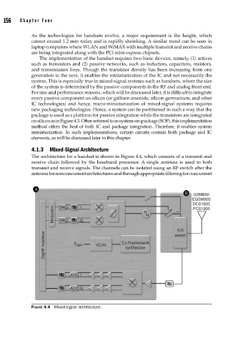
4.1.3 Mixed-Signal Architecture
The architecture for a handset is shown in Figure 4.4, which consists of a transmit and
receive chain followed by the baseband processor. A single antenna is used to both
transmit and receive signals. The channels can be isolated using an RF switch after the
antenna for nonconcurrent architectures and through appropriate filtering for concurrent
A
B GSM850
EGSM900
DCS1800
DAC
Modulator DAC Q
I
PCS1900
T/R
DigRF interface F REF VCX0 ∑Δ Fractional-N
switch
synthesizer
ADC I
ADC Q
FIGURE 4.4 Mixed-signal architecture.