Page 231 - System on Package_ Miniaturization of the Entire System
P. 231

Mixed-Signal (SOP) Design   205


                                    8000
                                    7000

                                    6000
                                   Mag(Zin) 5000
                                    4000

                                    3000
                                    2000

                                    1000
                                       0
                                        0   0.5  1    1.5  2   2.5  3    3.5  4
                                                     Frequency in GHz
                                                          (a)
                                      2
                                     1.5
                                      1
                                     0.5
                                   Phase(Zin)  −0.5 0


                                     −1
                                    −1.5
                                     −2
                                       0    0.5  1   1.5   2   2.5  3   3.5   4
                                                     Frequency in GHz
                                                          (b)
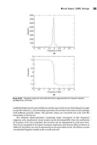
                    FIGURE 4.53  Frequency response and rational function approximation for one-port inductor.
                    (a) Magnitude. (b) Phase.


                    established between the physical layout and the equivalent circuit. Interestingly enough,
                    except for inductor L , the remaining equivalent circuits have the same circuit topology
                                      4
                    with different parasitic values. The parasitic values are consistent and scale with the
                    dimensions in the layout.
                       For arbitrary interconnections containing many resonances in the frequency
                    response, only nonphysical circuit models can be developed [58]. Once the coefficients
                    of Equation (4.21) are computed, the function can be represented in pole-zero form.
                    This can be expanded as low-pass, bandpass, high-pass, and all-pass filters as shown in
                    Table 4.8. Each filter can now be represented as an equivalent circuit. All of these circuits
                    concatenated together results in the overall network.
   226   227   228   229   230   231   232   233   234   235   236