
Page 233 - System on Package_ Miniaturization of the Entire System
P. 233
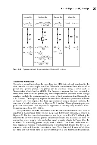
Mixed-Signal (SOP) Design   207


                    TABLE 4.8  Equivalent Circuit Representation of Rational Functions


                    Transient Simulation
                    The networks synthesized can be embedded in a SPICE circuit and simulated in the
                    time domain.  As an example, consider differential transmission lines referenced to
                    power and ground planes. The planes can be analyzed using a solver such as
                    Transmission Matrix Method (TMM). The frequency response has been extracted at
                    three ports defined on the planes [59], which represent the positions of the voltage
                    regulator module, the beginning and end points of the transmission line. This results in
                    a 3 × 3 matrix. The frequency response for two of the admittance parameters is shown
                    in Figure 4.55. The response has been approximated using a rational function, the
                    response of which is also shown in Figure 4.56. A total of 150 complex conjugate pole
                    pairs and 4 real poles were required to approximate the frequency response over a
                    frequency range from DC – 6 GHz.
                       The synthesized network constructed from the rational function has been used to
                    construct a macromodel (black box) of the power distribution network, as shown in
                    Figure 4.56. The time domain simulation can now be performed in SPICE [60] using the
                    macromodel of power-ground planes, differential drivers, and transmission lines for
                    computing power supply noise and other signal integrity effects. In Figure 4.56, the
                    schematic for simulating power supply noise is shown. The driver model used is a
                    time-dependent resistive switch representing four differential drivers. The drivers are
                    connected to four differential transmission lines. The differential drivers with 0.05-ns
                    rise time and 0.05-ns fall time are powered from port 2. The differential transmission