
Page 228 - System on Package_ Miniaturization of the Entire System
P. 228
202 Cha pte r F o u r
V2
Is2
V1
V4
Is1
V3
FIGURE 4.50 Stripline in an arbitrary multilayered structure.
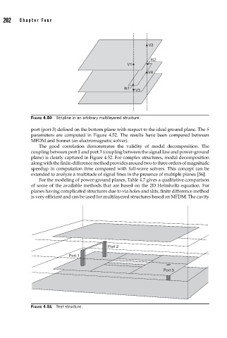
port (port 3) defined on the bottom plane with respect to the ideal ground plane. The S
parameters are computed in Figure 4.52. The results have been compared between
MFDM and Sonnet (an electromagnetic solver).
The good correlation demonstrates the validity of modal decomposition. The
coupling between port 1 and port 3 (coupling between the signal line and power-ground
plane) is clearly captured in Figure 4.52. For complex structures, modal decomposition
along with the finite-difference method provides around two to three orders of magnitude
speedup in computation time compared with full-wave solvers. This concept can be
extended to analyze a multitude of signal lines in the presence of multiple planes [56].
For the modeling of power-ground planes, Table 4.7 gives a qualitative comparison
of some of the available methods that are based on the 2D Helmholtz equation. For
planes having complicated structures due to via holes and slits, finite difference method
is very efficient and can be used for multilayered structures based on MFDM. The cavity
Port 2
Port 1
Port 3
FIGURE 4.51 Test structure.