
Page 225 - System on Package_ Miniaturization of the Entire System
P. 225
Mixed-Signal (SOP) Design 199
digital to the RF part of the system, either directly through the PDN or through the gap
between the split islands. This noise can also couple onto the digital signal lines, causing
interference in addition to crosstalk and reflections. It is therefore necessary to simulate
the digital signal lines in the presence of power and ground planes. In this section, the
modeling of signal and power delivery networks is discussed in the context of mixed-
signal modules (such as a mobile wireless communication unit), microprocessors, and
other high-speed communication links. A detailed description regarding the design and
analysis of power delivery networks can be found in [55a].
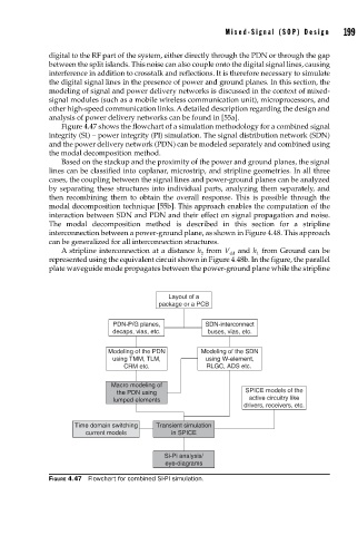
Figure 4.47 shows the flowchart of a simulation methodology for a combined signal
integrity (SI) – power integrity (PI) simulation. The signal distribution network (SDN)
and the power delivery network (PDN) can be modeled separately and combined using
the modal decomposition method.
Based on the stackup and the proximity of the power and ground planes, the signal
lines can be classified into coplanar, microstrip, and stripline geometries. In all three
cases, the coupling between the signal lines and power-ground planes can be analyzed
by separating these structures into individual parts, analyzing them separately, and
then recombining them to obtain the overall response. This is possible through the
modal decomposition technique [55b]. This approach enables the computation of the
interaction between SDN and PDN and their effect on signal propagation and noise.
The modal decomposition method is described in this section for a stripline
interconnection between a power-ground plane, as shown in Figure 4.48. This approach
can be generalized for all interconnection structures.
A stripline interconnection at a distance h from V and h from Ground can be
2
1
dd
represented using the equivalent circuit shown in Figure 4.48b. In the figure, the parallel
plate waveguide mode propagates between the power-ground plane while the stripline
Layout of a
package or a PCB
PDN-P/G planes, SDN-interconnect
decaps, vias, etc. buses, vias, etc.
Modeling of the PDN Modeling of the SDN
using TMM, TLM, using W-element,
CRM etc. RLGC, ADS etc.
Macro modeling of
the PDN using SPICE models of the
lumped elements active circuitry like
drivers, receivers, etc.
Time domain switching Transient simulation
current models in SPICE
Si-Pi analysis/
eye-diagrams
FIGURE 4.47 Flowchart for combined SI-PI simulation.