
Page 226 - System on Package_ Miniaturization of the Entire System
P. 226
200 Cha pte r F o u r
V dd
V 1 Parallel-plate V 2
h2 V dd ∗ V dd
∗
e r k Is 1 k Is 2
Is 1 Stripline Is 2
h1 k = − h1 Signal + + Signal
h1 + h2 ∗ ∗
Ground k V 1 k V 2
I 1 = = V 1
I 2 k Y = + Y kY V 2
2
= str = par str
I s1 = V s1
kY str Y str
I s2 V s2
(a) (b)
FIGURE 4.48 Modal decomposition of stripline. (a) Cross section. (b) Equivalent circuit.
mode propagates in the direction of the interconnection (assuming ideal planes). The
two modes can be combined to obtain the total voltages and currents through voltage
and current sources using the coefficient k. One way of representing this structure is by
using the admittance parameters, as shown in the figure. The voltages and currents can
also be computed in SPICE (or any circuit simulator) by using the equivalent circuit in
Figure 4.48b.
The Y parameters of the stripline mode (Y in Figure 4.48) can be extracted by using
str
a 2D or 3D electromagnetic solver and represented as a transmission line element in
SPICE. However, extraction of the frequency response of the power distribution is more
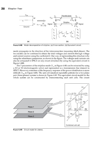
difficult (Y in Figure 4.48). The unit cell (smallest repeatable pattern) for a two-plane
par
pair (three planes) system is shown in Figure 4.49. The equivalent circuit model for the
whole system can be constructed by interconnecting such unit cells. The circuit
R1
L1 + L2 R1 L1 + L2 R1
L2
L2 G1
C1
L1 + L2
L2 R2
L2
Plane 1 L2
L2 R2 L2 R2
Plane 2
R2 G2
Plane 3 L2 C2
Combined unit cell
FIGURE 4.49 Circuit model for planes.