
Page 234 - System on Package_ Miniaturization of the Entire System
P. 234
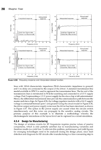
208    Cha pte r  F o u r


                   12                                    10                      Extrapolated
                                           Extrapolated
                        Interpolated response  response       Interpolated response  response
                   10
                                                          5
                  Real (Y22)  8 6                       Imaginary (Y22)  −5 0


                    4    Solid line: Orginal data              Solid line: Orginal data
                         Dotted line: Macromodel               Dotted line: Macromodel
                                                         −10
                    2
                                                         −15
                    0
                     0  1  2  3   4  5  6  7  8   9  10    0  1  2   3  4  5  6  7   8  9  10
                                Frequency (GHz)                       Frequency (GHz)
                                                          3
                   1.0                     Extrapolated                          Extrapolated
                        Interpolated response  response       Interpolated response  response
                                                          2
                   0.5                                    1
                 Real (Y23)  0                          Imaginary (Y22)  0


                  −0.5                                   −1
                         Solid line: Orginal data              Solid line: Orginal data
                         Dotted line: Macromodel               Dotted line: Macromodel
                  −1.0                                   −2
                                                         −3
                     0  1  2  3   4  5  6  7  8   9  10    0  1  2  3   4  5  6  7   8  9  10
                                Frequency (GHz)                       Frequency (GHz)
               FIGURE 4.55  Frequency response and interpolated rational function.


                    lines with 100-Ω characteristic impedance (50-Ω characteristic impedance to ground)
                    and 1-ns delay are connected to the output of the driver. A standard transmission line
                    model available in SPICE is used to represent the transmission lines. The far end of the
                    transmission lines is terminated in 50 Ω for matching and connected to a 0.3-V supply
                    voltage. Port 3 representing a 1.2-V power supply for the slave chip is left unterminated.
                    Hence, the differential transmission lines provide the communication path between the
                    master and slave chips. In Figure 4.56, the voltage regulator module with a 0.6-V supply
                    voltage is connected between port 1 and ground. Using the circuit model in Figure 4.56,
                    the driver output and power supply noise near the driver has been simulated, as shown
                    in Figure 4.57. The spikes in the power supply are caused when the circuits switch
                    simultaneously, and this noise can propagate to the sensitive analog circuits. The
                    primary purpose of this example is to illustrate a methodology whereby the
                    electromagnetic interactions at the layout level can be captured in a circuit simulation.

                    4.5.4  Design for Manufacturing
                    The design of wireless circuits for RF frequencies requires precise values of passive
                    components, which is only partially satisfied due to manufacturing variations and
                    therefore results in a yield loss. To alleviate this problem, performance and yield figures
                    for emerging technologies need to be analyzed during the design phase, since fault
                    detection and diagnosis for RF circuits after manufacturing is a time-consuming step in