
Page 302 - Introduction to chemical reaction engineering and kinetics
P. 302
11.2 Examples of Reactors for Illustration of Process Design Considerations 283
11.1.2 Mechanical Design
The distinction between process design (as outlined in Section 11.1.1) and “mechanical”
design (most other aspects!) is somewhat arbitrary. However, in the latter we include
the following, which, although important, are outside our scope in this book (see Perry,
et al., 1984; Peters and Timmerhaus, 1991):
impeller or agitator design (as in a stirred tank)
power requirement (for above)
reactor-as-pressure-vessel design
wall thickness
over-pressure relief
fabrication
support-structure design
maintenance features
11.2 EXAMPLES OF REACTORS FOR ILLUSTRATION OF PROCESS
DESIGN CONSIDERATIONS
Reactors exist in a variety of types with differing modes of operation for various pro-
cesses and reacting systems. Figures 11.1 to 11.8 illustrate a number of these, some in a
schematic, generic sense, and some for specific processes.
11.2.1 Batch Reactors
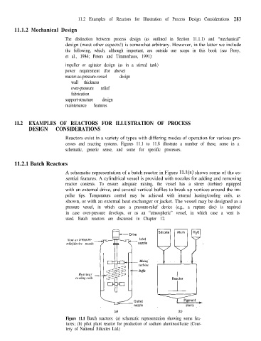
A schematic representation of a batch reactor in Figure ll.l(a) shows some of the es-
sential features. A cylindrical vessel is provided with nozzles for adding and removing
reactor contents. To ensure adequate mixing, the vessel has a stirrer (turbine) equipped
with an external drive, and several vertical baffles to break up vortices around the im-
peller tips. Temperature control may be achieved with internal heating/cooling coils, as
shown, or with an external heat exchanger or jacket. The vessel may be designed as a
pressure vessel, in which case a pressure-relief device (e.g., a rupture disc) is required
in case over-pressure develops, or as an “atmospheric” vessel, in which case a vent is
used. Batch reactors are discussed in Chapter 12.
Vent or pressure-
relief-device nozzle
Mixing
turbine
Baffle
Heating/ _
cooling coils
(a) (b)
Figure 11.1 Batch reactors: (a) schematic representation showing some fea-
tures; (b) pilot plant reactor for production of sodium aluminosilicate (Cour-
tesy of National Silicates Ltd.)