
Page 303 - Introduction to chemical reaction engineering and kinetics
P. 303
284 Chapter 11: Preliminary Considerations in Chemical Reaction Engineering
Figure ll.l(b) illustrates a pilot plant batch reactor used in the early 1990s for the
production of sodium aluminosilicate, from alum and sodium silicate, for use in the
pulp and paper industry. The ratio of SiO, to Al,O, in the product is controlled by
adjustment of the feed amounts from the hoppers above the reactor. Efficient mixing
is required for the reacting system (a non-Newtonian slurry) to produce the desired
amorphous form. For this, baffles on the walls and mixing paddles (not shown) on the
central shaft are used. After an appropriate reaction time, the pigment slurry (interme-
diate product) is removed for further processing.
11.2.2 Stirred-Tank Flow Reactors
A stirred-tank flow reactor may be single-stage or multistage. As an ideal backmix flow
reactor, it is referred to as a CSTR or multistage CSTR; this is treated in Chapter 14.
Nonideal flow effects are discussed in Chapter 20.
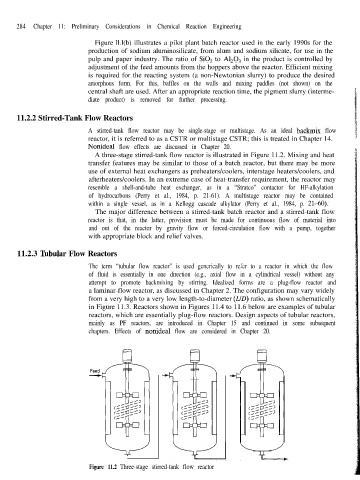
A three-stage stirred-tank flow reactor is illustrated in Figure 11.2. Mixing and heat
transfer features may be similar to those of a batch reactor, but there may be more
use of external heat exchangers as preheaters/coolers, interstage heaters/coolers, and
afterheaters/coolers. In an extreme case of heat-transfer requirement, the reactor may
resemble a shell-and-tube heat exchanger, as in a “Stratco” contactor for HF-alkylation
of hydrocarbons (Perry et al., 1984, p. 21-61). A multistage reactor may be contained
within a single vessel, as in a Kellogg cascade alkylator (Perry et al., 1984, p. 21-60).
The major difference between a stirred-tank batch reactor and a stirred-tank flow
reactor is that, in the latter, provision must be made for continuous flow of material into
and out of the reactor by gravity flow or forced-circulation flow with a pump, together
with appropriate block and relief valves.
11.2.3 ‘Ihbular Flow Reactors
The term “tubular flow reactor” is used generically to refer to a reactor in which the flow
of fluid is essentially in one direction (e.g., axial flow in a cylindrical vessel) without any
attempt to promote backmixing by stirring. Idealized forms are a plug-flow reactor and
a laminar-flow reactor, as discussed in Chapter 2. The configuration may vary widely
from a very high to a very low length-to-diameter (LID) ratio, as shown schematically
in Figure 11.3. Reactors shown in Figures 11.4 to 11.6 below are examples of tubular
reactors, which are essentially plug-flow reactors. Design aspects of tubular reactors,
mainly as PF reactors, are introduced in Chapter 15 and continued in some subsequent
chapters. Effects of nonideal flow are considered in Chapter 20.
\
Figure 11.2 Three-stage stirred-tank flow reactor