
Page 308 - Introduction to chemical reaction engineering and kinetics
P. 308
11.2 Examples of Reactors for Illustration of Process Design Considerations 289
second uses quench cooling. In the latter, part of the cool reactor feed gas is added to
the main gas stream at intervals along the length of a bed, usually between stages. This
is achieved by means of the “lozenge” distributors shown. Figure llS(c) shows a con-
verter employing radial flow of gas through each of two beds (together with cooling by
heat exchangers); the flow is radially inward from the outer perimeter. The advantage
of radial flow relative to axial flow is that the resulting pressure drop (and hence, power
consumption) is lower, because the flow area is greater and the path length smaller. Fig-
ure llS(d) illustrates “cross-flow” of gas through three beds in a horizontal converter
with cooling by heat exchange.
Some of the many design aspects of fixed-bed catalytic reactors are indicated in Fig-
ure 11.5. These and other aspects are taken up in Chapter 21.
11.2.3.3 Fixed-Bed Catalytic Reactors: Methanol Synthesis
The synthesis of methanol, CO + 2H, = CH,OH, like ammonia synthesis, is an exother-
mic, reversible, catalytic reaction. Unlike a catalyst for ammonia synthesis, a catalyst for
Tubecooled T
(a) (b)
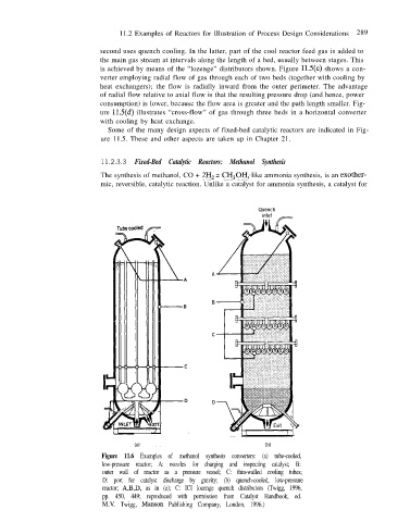
Figure 11.6 Examples of methanol synthesis converters: (a) tube-cooled,
low-pressure reactor; A: nozzles for charging and inspecting catalyst; B:
outer wall of reactor as a pressure vessel; C: thin-walled cooling tubes;
D: port for catalyst discharge by gravity; (b) quench-cooled, low-pressure
reactor; A,B,D, as in (a); C: ICI lozenge quench distributors (Twigg, 1996,
pp. 450, 449; reproduced with permission from Catalyst Handbook, ed.
M.V. Twigg, Manson Publishing Company, London, 1996.)