
Page 151 - Sami Franssila Introduction to Microfabrication
P. 151
130 Introduction to Microfabrication
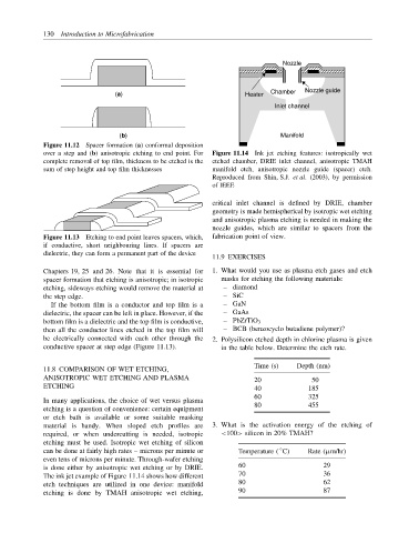
Nozzle
(a) Heater Chamber Nozzle guide
Inlet channel
(b) Manifold
Figure 11.12 Spacer formation (a) conformal deposition
over a step and (b) anisotropic etching to end point. For Figure 11.14 Ink jet etching features: isotropically wet
complete removal of top film, thickness to be etched is the etched chamber, DRIE inlet channel, anisotropic TMAH
sum of step height and top film thicknesses manifold etch, anisotropic nozzle guide (spacer) etch.
Reproduced from Shin, S.J. et al. (2003), by permission
of IEEE
critical inlet channel is defined by DRIE, chamber
geometry is made hemispherical by isotropic wet etching
and anisotropic plasma etching is needed in making the
nozzle guides, which are similar to spacers from the
Figure 11.13 Etching to end point leaves spacers, which, fabrication point of view.
if conductive, short neighbouring lines. If spacers are
dielectric, they can form a permanent part of the device
11.9 EXERCISES
Chapters 19, 25 and 26. Note that it is essential for 1. What would you use as plasma etch gases and etch
spacer formation that etching is anisotropic; in isotropic masks for etching the following materials:
etching, sideways etching would remove the material at – diamond
the step edge. – SiC
If the bottom film is a conductor and top film is a – GaN
dielectric, the spacer can be left in place. However, if the – GaAs
bottom film is a dielectric and the top film is conductive, – PbZrTiO 3
then all the conductor lines etched in the top film will – BCB (benzocyclo butadiene polymer)?
be electrically connected with each other through the 2. Polysilicon etched depth in chlorine plasma is given
conductive spacer at step edge (Figure 11.13). in the table below. Determine the etch rate.
Time (s) Depth (nm)
11.8 COMPARISON OF WET ETCHING,
ANISOTROPIC WET ETCHING AND PLASMA 20 50
ETCHING 40 185
60 325
In many applications, the choice of wet versus plasma
etching is a question of convenience: certain equipment 80 455
or etch bath is available or some suitable masking
material is handy. When sloped etch profiles are 3. What is the activation energy of the etching of
required, or when undercutting is needed, isotropic <100> silicon in 20% TMAH?
etching must be used. Isotropic wet etching of silicon
◦
can be done at fairly high rates – microns per minute or Temperature ( C) Rate (µm/hr)
even tens of microns per minute. Through-wafer etching
is done either by anisotropic wet etching or by DRIE. 60 29
The ink jet example of Figure 11.14 shows how different 70 36
etch techniques are utilized in one device: manifold 80 62
etching is done by TMAH anisotropic wet etching, 90 87