
Page 155 - Know and Understand Centrifugal Pumps
P. 155
Know and Understand Centrifugal Pumps
2. You may see the same evidence all around the circumference of the
close tolerance rotary elements, with gouge or wear spots on the
stationary elements at about 240" from the pump cutwater.
These marks are caused or induced by operations or by design.
This evidence is revealed when operating the pump too far to
the right of the BEP on its curve. Perhaps the pump is
inadequate and doesn't meet the flow and head requirements of
the system. It could also be that there is a loss of resistance in
the discharge piping. A big hole in the discharge piping could
present the same evidence.
If you must live with this condition, you need to increase the
diameter of the shaft to improve the L/D factor and deflection
resistance.
3. If you see the same evidence, gouge and wear marks around the
circumference of close tolerance rotary elements, and spots or arcs
on the close tolerance stationary elements at about 180" from the
cutwater, or straight down:
This would be a problem induced by inadequate design, caused
by pipe strain probably in a high temperature (thermal
expansion) application. The volute of the pump and the
stationary elements are growing up from the floor due to
thermal expansion, against the rotary elements. You need to
speak with the plant engineer and show him the evidence. A
possible solution is to change your ANSI standard pump for a
'High Temperature' or API design in this application.
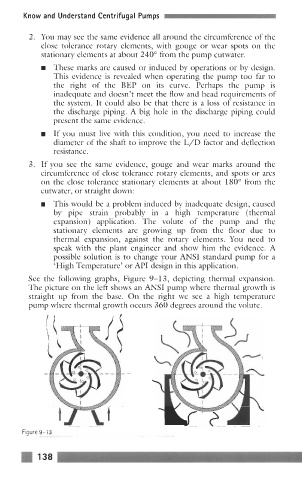
See the following graphs, Figure 9-1 3, depicting thermal expansion.
The picture on the left shows an ANSI pump where thermal growth is
straight up from the base. On the right we see a high temperature
pump where thermal growth occurs 360 degrees around the volute.