
Page 255 - Lindens Handbook of Batteries
P. 255
MAGNeSiUM AND ALUMiNUM bATTerieS 10.7
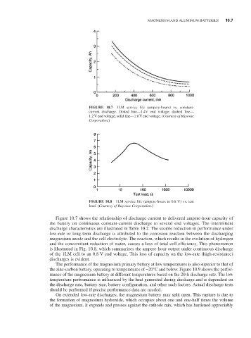
FIGURE 10.7 1LM service life (ampere-hours) vs. constant-
current discharge. Dotted line—1.4V end voltage; dashed line—
1.2 V end voltage; solid line—1.0 V end voltage. (Courtesy of Rayovac
Corporation.)
FIGURE 10.8 1LM service life (ampere-hours to 0.8 V) vs. test
load. (Courtesy of Rayovac Corporation.)
Figure 10.7 shows the relationship of discharge current to delivered ampere-hour capacity of
the battery on continuous constant-current discharge to several end voltages. The intermittent
discharge characteristics are illustrated in Table 10.2. The sizable reduction in performance under
low-rate or long-term discharge is attributed to the corrosion reaction between the discharging
magnesium anode and the cell electrolyte. The reaction, which results in the evolution of hydrogen
and the concomitant reduction of water, causes a loss of total cell efficiency. This phenomenon
is illustrated in Fig. 10.8, which summarizes the ampere-hour output under continuous discharge
of the 1LM cell to an 0.8 V end voltage. This loss of capacity on the low-rate (high-resistance)
discharges is evident.
The performance of the magnesium primary battery at low temperatures is also superior to that of
the zinc-carbon battery, operating to temperatures of -20°C and below. Figure 10.9 shows the perfor-
mance of the magnesium battery at different temperatures based on the 20-h discharge rate. The low
temperature performance is influenced by the heat generated during discharge and is dependent on
the discharge rate, battery size, battery configuration, and other such factors. Actual discharge tests
should be performed if precise performance data are needed.
On extended low-rate discharges, the magnesium battery may split open. This rupture is due to
the formation of magnesium hydroxide, which occupies about one and one-half times the volume
of the magnesium. it expands and presses against the cathode mix, which has hardened appreciably