
Page 102 - Low Temperature Energy Systems with Applications of Renewable Energy
P. 102
Effective use of heat pumps for various heating applications 91
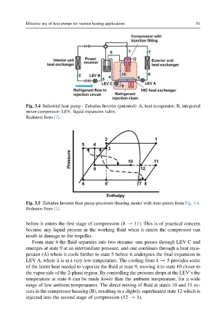
Fig. 3.4 Industrial heat pump - Zubadan Inverter (patented): A, heat recuperator; B, integrated
mixer-compressor; LEV, liquid expansion valve.
Redrawn from [2].
Fig. 3.5 Zubadan Inverter heat pump processes (heating mode) with state-points from Fig. 3.4.
Redrawn from [2].
before it enters the first stage of compression (8 / 11). This is of practical concern
because any liquid present in the working fluid when it enters the compressor can
result in damage to the impeller.
From state 4 the fluid separates into two streams: one passes through LEV C and
emerges at state 9 at an intermediate pressure, and one continues through a heat recu-
perator (A) where it cools further to state 5 before it undergoes the final expansion in
LEV A, where it is at a very low temperature. The cooling from 4 / 5 provides some
of the latent heat needed to vaporize the fluid at state 9, moving it to state 10 closer to
the vapor side of the 2-phase region. By controlling the pressure drops at the LEV’s the
temperature at state 6 can be made lower than the ambient temperature, for a wide
range of low ambient temperatures. The direct mixing of fluid at states 10 and 11 oc-
curs in the compressor housing (B), resulting in a slightly superheated state 12 which is
injected into the second stage of compression (12 / 1).