
Page 103 - Low Temperature Energy Systems with Applications of Renewable Energy
P. 103
92 Low-Temperature Energy Systems with Applications of Renewable Energy
Thus, triple-expansion of the liquid refrigerant results in a very low fluid tempera-
ture as it enters the evaporator, allowing heat transfer from the surroundings even at
low ambient temperatures. Furthermore, using a 2-stage compressor with effective
interstage cooling results in less power needed for the compressor. Both of these ef-
fects extend the range of the heat pump and increase its COP compared to a simple
system. There are other practical advantages such as guaranteeing that only vapor en-
ters the compressor impeller and that only liquid enters the expansion valves [2].
3.1.3 Combined heat pump systems
In temperate and northern climatic zones, heat pumps of the “earth-water" (or “ground-
to-water”) and “water-to-water" type are used to avoid the low ambient air temperature
problem. Combined heat pump units include various energy sources such as solar en-
ergy, heat of waste water and sewages, heat of water crystallization, ventilated air, etc.
When using heat pumps, various low-temperature renewable energy sources are used
to reduce capital and operating costs. However, the use of various energy sources re-
duces the energy capacity of heat pump units by 25e30% compared to conventional
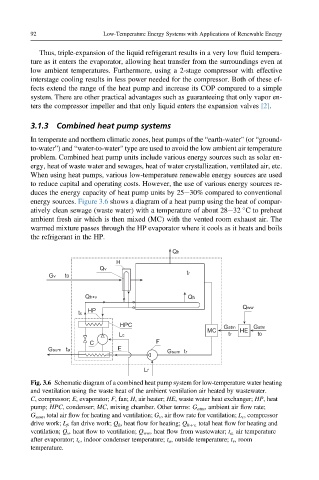
energy sources. Figure 3.6 shows a diagram of a heat pump using the heat of compar-
atively clean sewage (waste water) with a temperature of about 28e32 C to preheat
ambient fresh air which is then mixed (MC) with the vented room exhaust air. The
warmed mixture passes through the HP evaporator where it cools as it heats and boils
the refrigerant in the HP.
Qh
H
Qv
tr
Gv t0
Qh+v Qh
Qww
HP
tc
HPC Gatm Gatm
MC HE
Lc tr t0
C F
Gsum ta E
Gsum tr
Lf
Fig. 3.6 Schematic diagram of a combined heat pump system for low-temperature water heating
and ventilation using the waste heat of the ambient ventilation air heated by wastewater.
C, compressor; E, evaporator; F, fan; H, air heater; HE, waste water heat exchanger; HP, heat
pump; HPC, condenser; MC, mixing chamber. Other terms: G atm , ambient air flow rate;
G sum , total air flow for heating and ventilation; G v , air flow rate for ventilation; L c , compressor
drive work; L f , fan drive work; Q h , heat flow for heating; Q hþv, total heat flow for heating and
ventilation; Q v , heat flow to ventilation; Q ww , heat flow from wastewater; t a, air temperature
after evaporator; t c , indoor condenser temperature; t o , outside temperature; t r , room
temperature.