
Page 147 - Low Temperature Energy Systems with Applications of Renewable Energy
P. 147
Heat pumps in the drying industry 137
Fig. 4.2 Schematic diagram of a (A) basic drying plant and (B) one with a heat recuperator.
temperature as needed. See Fig. 4.2A. The figure also shows a recuperated system
(B) that will be described shortly.
Before moving on to more complex systems, we present a graphical method to
analyze the basic case. Consider the adiabatic drying process which takes place in a
dryer operating on the basic scheme (Fig. 4.2A), i.e., the air is heated in an air heater
and then makes a single pass through the drying chamber. The processes may be visu-
alized in a psychrometric chart (PC) (Fig. 4.3) that presents the properties of moist air
in coordinates of moisture content (ordinate) versus the dry-bulb temperature (ab-
scissa) [14,15]. The curved lines that fan out and upward from the lower left represent
lines of constant relative humidity, with the highest one being 100%. In this figure,
point 1 is determined from the properties of the ambient air. Assume that the ambient
air temperature, t 1 ¼ 20 C and moisture content is 0.10 kg/kg dry air; from the PC one
can read that the relative humidity is w70%. The process of heating the air prior to the
0
0
dryer is represented by line 1 / 2 , where point 2 is determined by the assumed
00
0
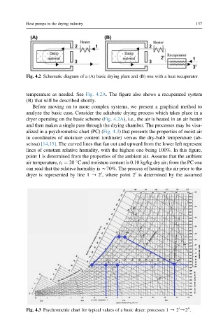
Fig. 4.3 Psychrometric chart for typical values of a basic dryer: processes 1 / 2 /2 .