
Page 149 - Low Temperature Energy Systems with Applications of Renewable Energy
P. 149
Heat pumps in the drying industry 139
refrigerant). The refrigerant vapor is compressed in the compressor and enters the
condenser. As the vapor condenses, it heats up the ambient air entering the dryer.
4.1.4 Case D: Open system using ambient air with a heat pump
and auxiliary heater
If it is impossible to heat the air to the required temperature in the condenser using the
VCHP system in Case C, a supplementary electric heater is installed (Fig. 4.4D).
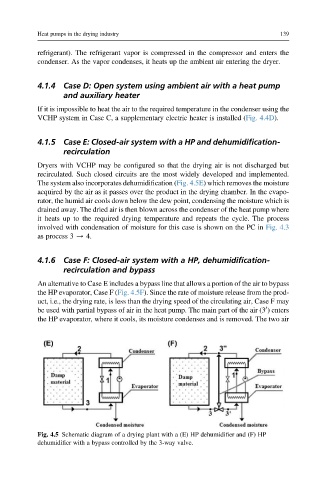
4.1.5 Case E: Closed-air system with a HP and dehumidification-
recirculation
Dryers with VCHP may be configured so that the drying air is not discharged but
recirculated. Such closed circuits are the most widely developed and implemented.
The system also incorporates dehumidification (Fig. 4.5E) which removes the moisture
acquired by the air as it passes over the product in the drying chamber. In the evapo-
rator, the humid air cools down below the dew point, condensing the moisture which is
drained away. The dried air is then blown across the condenser of the heat pump where
it heats up to the required drying temperature and repeats the cycle. The process
involved with condensation of moisture for this case is shown on the PC in Fig. 4.3
as process 3 / 4.
4.1.6 Case F: Closed-air system with a HP, dehumidification-
recirculation and bypass
An alternative to Case E includes a bypass line that allows a portion of the air to bypass
the HP evaporator, Case F (Fig. 4.5F). Since the rate of moisture release from the prod-
uct, i.e., the drying rate, is less than the drying speed of the circulating air, Case F may
be used with partial bypass of air in the heat pump. The main part of the air (3 ) enters
0
the HP evaporator, where it cools, its moisture condenses and is removed. The two air
Fig. 4.5 Schematic diagram of a drying plant with a (E) HP dehumidifier and (F) HP
dehumidifier with a bypass controlled by the 3-way valve.