
Page 151 - Low Temperature Energy Systems with Applications of Renewable Energy
P. 151
Heat pumps in the drying industry 141
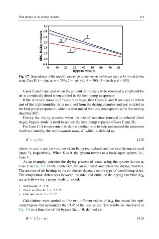
Fig. 4.7 Dependence of the specific energy consumption on the bypass ratio a for wood drying
using Case F: 1 ¼ pine at f ¼ 75%; 2 ¼ oak with f ¼ 70%; 3 ¼ larch at f ¼ 85%.
Cases E and F are used when the amount of moisture to be removed is small and the
air is completely dried when cooled in the heat pump evaporator.
If the removed amount of moisture is large, then Cases G and H are used in which
part of the high-humidity air is removed from the drying chamber and part is dried in
the heat pump evaporator, which is then mixed with dry atmospheric air in the mixing
chamber MC.
During the drying process, when the rate of moisture removal is reduced (final
stage), bypass mode is used to reduce the heat pump capacity (Cases F and H).
For Case G, it is convenient to define another ratio to help understand the processes
involved, namely, the recirculation ratio, K, which is defined as:
K ¼ v 3 =v 3 ; (4.2)
0
where v 3 and v 3 are the volumes of air being recirculated and the total drying air used
0
(state 3), respectively. When K ¼ 0, the system reverts to a basic open system, i.e.,
Case C.
As an example, consider the drying process of wood using the system shown as
Case F in Fig. 4.5. In the condenser, the air is heated and enters the drying chamber.
The amount of air heating in the condenser depends on the type of wood being dried.
The temperature differences between the inlet and outlet of the drying chamber Dt dc
are as follows for various kinds of wood:
• Softwoods: 2e3 C
• Birch and beech: 1.5e2.5 C
• Oak and larch: 1e1.5 C.
Calculations were carried out for two different values of Dt dc that reveal the opti-
mum bypass that maximizes the COP of the heat pump. The results are displayed in
Fig. 4.8 as a function of the bypass factor B,defined as:
B ¼ 1=ð1 aÞ (4.3)