
Page 165 - MEMS Mechanical Sensors
P. 165
154 Force and Torque Sensors
gauges can be relatively labor intensive and skilled, and may require relatively ineffi-
cient calibration procedures.
In recent years some instrument manufacturers of force and torque measure-
ment devices have moved away from using resistance strain gauges. Already, one
leading manufacturer of weighing machines for retail and industrial applications
now uses metallic and quartz resonant tuning fork technologies, and smaller compa-
nies have established niche markets using surface acoustic wave (SAW) technology,
optical technology, and magnetoelastic technology.
Further commercial developments are taking place to enhance device manufac-
turability and improve device sensitivity and robustness in operation. Measurement
on stiffer structures at much lower strain levels is now possible. The worldwide sen-
sor research base is very active in exploring MEMS for sensing force and torque, and
the rest of this chapter will review the current situation and future prospects.
7.2 Silicon-Based Devices
Strain gauges based on semiconductor materials such as silicon have been used for a
long time, and although they are rather more expensive and more difficult to apply
to a surface than metal strain gauges, their big advantage is a very high gauge factor
of about ±130, allowing measurement of small strain (e.g., 0.01 microstrain). It
should be noted that the same factor for metal strain gauges is about 2. In semicon-
ductor gauges most of the resistance change comes from the piezoresistance effect
[5]. This gauge is rather nonlinear at comparatively high strain levels—that is, the
gauge factor varies with strain. For example, if the gauge factor is 130 at 0.2% of
strain, then it is about 112 at 0.4% of strain, which is the elastic limit of the gauge.
Also, the gauge factor varies significantly with temperature about –0.15%/°C,
which is more than 10 times worse than the metal gauges. This temperature sensitiv-
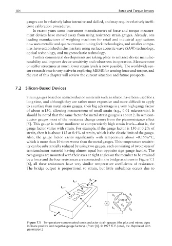
ity can be substantially reduced by using two gauges, each consisting of two pieces of
semiconductor material having almost equal but opposite sign gauge factors. The
two gauges are mounted with their axes at right angles on the member to be strained
by a force and the four resistances are connected in the bridge as shown in Figure 7.1
[6], all these resistances have very similar temperature coefficients of resistance.
The bridge output is proportional to strain, but little unbalance occurs due to
R −
R+ 4
3
R −
2
R 3 R 1
Output
V s V
R+ R 4 o R 2
1
Figure 7.1 Temperature-compensated semiconductor strain gauges (the plus and minus signs
indicate positive and negative gauge factors). (From: [6]. © 1977 B. E. Jones, Inc. Reprinted with
permission.)