
Page 170 - MEMS Mechanical Sensors
P. 170
7.4 Optical Devices 159
resonant structure vibrated with an amplitude of 100 nm in resonance at about 104
kHz with a Q of 30,000. Load sensitivity was about 4,000 Hz/N.
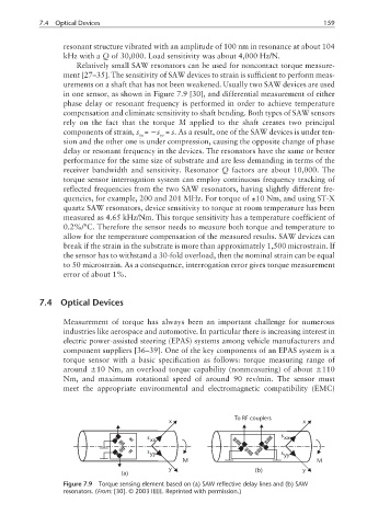
Relatively small SAW resonators can be used for noncontact torque measure-
ment [27–35]. The sensitivity of SAW devices to strain is sufficient to perform meas-
urements on a shaft that has not been weakened. Usually two SAW devices are used
in one sensor, as shown in Figure 7.9 [30], and differential measurement of either
phase delay or resonant frequency is performed in order to achieve temperature
compensation and eliminate sensitivity to shaft bending. Both types of SAW sensors
rely on the fact that the torque M applied to the shaft creates two principal
components of strain,s = −s = s. As a result, one of the SAW devices is under ten-
xx yy
sion and the other one is under compression, causing the opposite change of phase
delay or resonant frequency in the devices. The resonators have the same or better
performance for the same size of substrate and are less demanding in terms of the
receiver bandwidth and sensitivity. Resonator Q factors are about 10,000. The
torque sensor interrogation system can employ continuous frequency tracking of
reflected frequencies from the two SAW resonators, having slightly different fre-
quencies, for example, 200 and 201 MHz. For torque of ±10 Nm, and using ST-X
quartz SAW resonators, device sensitivity to torque at room temperature has been
measured as 4.65 kHz/Nm. This torque sensitivity has a temperature coefficient of
0.2%/°C. Therefore the sensor needs to measure both torque and temperature to
allow for the temperature compensation of the measured results. SAW devices can
break if the strain in the substrate is more than approximately 1,500 microstrain. If
the sensor has to withstand a 30-fold overload, then the nominal strain can be equal
to 50 microstrain. As a consequence, interrogation error gives torque measurement
error of about 1%.
7.4 Optical Devices
Measurement of torque has always been an important challenge for numerous
industries like aerospace and automotive. In particular there is increasing interest in
electric power-assisted steering (EPAS) systems among vehicle manufacturers and
component suppliers [36–39]. One of the key components of an EPAS system is a
torque sensor with a basic specification as follows: torque measuring range of
around ±10 Nm, an overload torque capability (nonmeasuring) of about ±110
Nm, and maximum rotational speed of around 90 rev/min. The sensor must
meet the appropriate environmental and electromagnetic compatibility (EMC)
To RF couplers
x x
s xx s xx
s yy s yy
M M
y (b) y
(a)
Figure 7.9 Torque sensing element based on (a) SAW reflective delay lines and (b) SAW
resonators. (From: [30]. © 2003 IEEE. Reprinted with permission.)