
Page 175 - MEMS Mechanical Sensors
P. 175
164 Force and Torque Sensors
has been designed to detect torque with respect to two axes, x and y. The legs have
slits to improve sensitivity of the levers. The levers protrude from a carrier chip that
is etched out of the silicon wafer. Dimensions are as follows: L = 200 µm,l = 100 µm,
w =10 µm, p =4 µm, b = 117 µm, t (thickness) = 5 µm. Two piezoresistors R and R
1 2
are defined by doping the silicon locally with boron. A flexion and/or torsion of the
lever creates a mechanical stress in the beams, which changes the resistance of the
piezoresistors by ∆R owing to the piezoresistive effect. The torque about the x-axis
can be extracted by measuring ∆(R – R ). The torsion creates stress with the oppo-
1 2
site sign symmetrically around a location at the middle of the lever. Sensitivity
–6
(∆R/R) to torsion has a value 1.5 × 10 per pNm. Piezoresistance values are typi-
cally 2 to 3 kΩ and resonance frequency is about 78 kHz, and so the device has a
short response time. Sensitivity is high (up to ≈10 –14 Nm). An external magnetic field
applied to the sample having a magnetic moment generates a torque on it and to the
cantilever.
7.7 Atomic Force Microscope and Scanning Probes
There is a growing need to measure and characterize finer and finer surfaces. This
requirement imposes considerable demands on the instruments that measure and
characterize these surfaces. The scanning force microscope (SFM), which includes
the atomic force microscope (AFM), has become a well-established technique for the
analysis of surfaces. Basically, a cantilever either dynamically in vibration scans
across a sample surface or scans across the surface in a static contacting mode. The
cyclic contact SFM may not damage the surface of soft samples as does the contact
SFM. Miniaturized standalone SFMs are needed for use in wafer inspection, ultra-
high vacuum SFM, and liquid environments. The cantilever deflection sensing and
alignment maintenance arrangements during scanning need to be small. Force-
sensing cantilevers for miniaturized SFMs include the following: the piezoresistive
type, the piezoelectric type, and the capacitive type. The piezoelectric cantilever can
perform the actuation of z-axis tip-sample spacing by a superimposed dc voltage,
when the cantilever executes the self-force sensing at the same time. For the minia-
turized dynamic SFMs, the use of the piezoelectric cantilever enables the necessary
components to become just one piezoelectric microcantilever and an x-y axes
scanner [62].
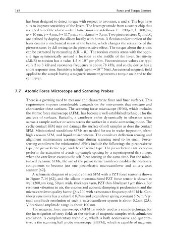
A schematic diagram of a cyclic contact SFM with a PZT force sensor is shown
in Figure 7.14 [62], and the silicon micromachined PZT force sensor is shown as
well (200 µm long, 50 µm wide, thickness 4 µm, PZT thin-film layer 1 µm thick). For
resonant vibration in air, the viscous and acoustic damping is predominant and the
micro-cantilever quality factor Q is 200 with a resonance frequency of 60 kHz. Can-
tilever sensitivity has a value 0.6 fC/nm and a cantilever spring constant 5 N/m. Ver-
tical amplitude resolution of such a microcantilever system is about 0.2nm (2Å).
Vibrational amplitude range is about 100 nm.
The magnetic force microscope (MFM) is widely used as a simple technique for
the investigation of stray fields at the surface of magnetic samples with submicron
resolution. A complementary technique, which is both noninvasive and quantita-
tive, is the scanning hall probe microscope (SHPM), which is capable of magnetic