
Page 174 - MEMS Mechanical Sensors
P. 174
7.6 Magnetic Devices 163
Coils
NiFe
SiO 2
Si
CoSiB-Ribbon CMOS-MAGFETs
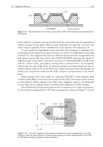
Figure 7.12 Micromachined sensor head. (From: [56]. © 1995 IOP Publishing Ltd. Reprinted with
permission.)
arises with the variation of the air gap between the sensor head and the amorphous
ribbon attached to the shaft. These air gap variations are typically ±10 µm, and
when torque is applied, there is modulation of the signal of the induction coil.
A very small micromachined sensor head has been designed to eliminate this
modulation of the signal by air gap variation, by means of a differential measuring
method [57]. The magnetic flux density is directly measured in the air gap under the
pole pieces and in the stray field with CMOS-MAGFETs because the signal of
induction coils is too small. This device consists of CMOS-MAGFETs at the front
side of a silicon wafer, and planar exciting coils, combined with a ferromagnetic
yoke at the rear side of the wafer. To measure torque, two sensor heads are reposi-
tioned with an angle ±45° to the shaft axis. These directions show the maxima of
tensile and compressive stress on the shaft. Torque is proportional to the tensile
stress.
Improvements have been made by replacing MAGFETs with magnetic field
resistors (MAGRES), which have lower noise levels [60]. This torque sensor system
is fabricated in silicon—planar coils, NiFe yoke, magnetic sensors—all integrated
on one chip, thus avoiding common problems like telemetry or bulky designs.
Microfabricated ultrasensitive piezoresistive cantilevers for torque magnetome-
try have been investigated [61]. The basic arrangement is shown in Figure 7.13 and
Contact
Sample Slit B Slit A
R 1
Metal
b
w p R 2
l
Edge of chip
y
x L
Figure 7.13 Schematic diagram of piezoelectric cantilever for torque magnetometry: two-leg
cantilever with two piezoresistors for measuring bending and torsion independently. (From: [61].
© 1999 Elsevier Science. Reprinted with permission.)