
Page 176 - MEMS Mechanical Sensors
P. 176
7.7 Atomic Force Microscope and Scanning Probes 165
Micromachined
PZT force sensor
Frequency
synthesizer
Ref.
Lock-in
Oscillator amplifier
Charge
amplifier
Asin φ
φ
Sample (Acos )
Tube scanner Controller
Figure 7.14 Schematic diagram of a cyclic contact SFM with a PZT force sensor using the
piezoelectric charge detection method. (From: [62]. © 1997 American Institute of Physics.
Reprinted with permission.)
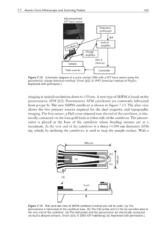
imaging at spatial resolutions down to 150 nm. A new type of SHPM is based on the
piezoresistive AFM [63]. Piezoresistive AFM cantilevers are commonly fabricated
from p-type Si. The new SHPM cantilever is shown in Figure 7.15. The plan view
shows the two primary sensors required for the dual magnetic and topographic
imaging. The first sensor, a Hall cross-situated near the end of the cantilever, is elec-
trically contacted via the four gold leads at either side of the cantilever. The piezore-
sistor is placed at the base of the cantilever where bending stresses are at a
maximum. At the very end of the cantilever is a sharp (<100-nm diameter) AFM
tip, which, by inclining the cantilever, is used to map the sample surface. With a
µ
400 m
(b)
m
(a) µ
160
(c)
(d)
µ
5m
Figure 7.15 Plan and side view of SHPM cantilever (vertical axis not to scale). (a) The
piezoresistor is fabricated at the cantilever base. (b) The Hall probe and (c) the tip are fabricated at
the very end of the cantilever. (d) The Hall probe and the piezoresistor are electrically contacted
via Au/Ge alloyed contacts. (From: [63]. © 2003 IOP Publishing Ltd. Reprinted with permission.)