
Page 173 - MEMS Mechanical Sensors
P. 173
162 Force and Torque Sensors
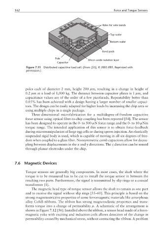
Holes for wire bonds
Top wafer
Bottom wafer
Bond pads
Pole
Silicon oxide isolation layer
Capacitor
Figure 7.11 Distributed capacitive load cell. (From: [53]. © 2003 IEEE. Reprinted with
permission.)
poles each of diameter 2 mm, height 200 µm, resulting in a change in height of
0.2 µm at a load of 1,000 kg. The distance between capacitor plates is 1 µm, and
capacitance values are of the order of a few picofarads. Repeatability better than
0.05% has been achieved with a design having a larger number of smaller capaci-
tors. The design can be easily adapted for higher loads by increasing the chip area or
using multiple chips in a single package.
Three-dimensional microfabrication for a multidegree-of-freedom capacitive
force sensor using optical fiber-to-chip coupling has been reported [54]. The sensor
has been designed to operate in the 0- to 500-µN force range and the 0- to 10-µNm
torque range. The intended application of this sensor is to obtain force-feedback
during micromanipulation of large egg cells or during sperm injection. An elastically
suspended rigid body is used, which is capable of moving in all six degrees of free-
dom when coupled to a glass fiber. Nonsymmetric comb capacitors allow for decou-
pling between displacements in the x and y directions. The z direction can be sensed
through planar electrodes under the chip.
7.6 Magnetic Devices
Torque sensors are generally big components. In most cases, the shaft where the
torque is to be measured has to be cut to install the torque sensor in between the
resulting two parts. Furthermore, the signal is transmitted by slip rings or a coaxial
transformer [1].
The magnetic head type of torque sensor allows the shaft to remain as one part
and to receive the signal without slip rings [55–60]. This principle is based on the
strong magnetostrictive properties of some ferromagnetic materials like amorphous
alloy CoSiB ribbons. The ribbon has strong magnetoelastic properties and trans-
forms torque into a change of permeability µ. A schematic of the arrangement is
shown in Figure 7.12 [56]. Installed above the ribbon, a sensor head made of a ferro-
magnetic yoke with exciting and induction coils allows detection of the change in
permeability caused by mechanical stress, without contacting the ribbon. A problem