
Page 172 - MEMS Mechanical Sensors
P. 172
7.5 Capacitive Devices 161
and electromagnetic interference can be a problem [49, 50]. Torque can be meas-
ured by the use of a set of electrodes on one end of a torsion bar connected to a shaft
and a second set of electrodes on the outside of a thin tube of dielectric material
[51]. This tube is fixed to the shaft at the other end of the torsion bar. One set of
electrodes moves with respect to the second set when torque is applied such that
there is capacitance variation between the two sets of electrodes. The capacitance is
part of a resonance circuit inductively linked to a coil on the stationary part. Each
end of a torsion bar can have a noncontact capacitive angular displacement sensor,
and the torque twist is monitored by electrical phase change.
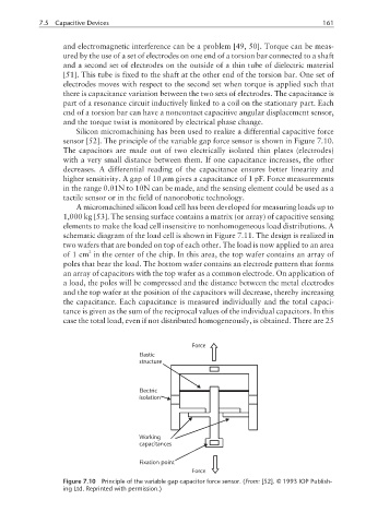
Silicon micromachining has been used to realize a differential capacitive force
sensor [52]. The principle of the variable gap force sensor is shown in Figure 7.10.
The capacitors are made out of two electrically isolated thin plates (electrodes)
with a very small distance between them. If one capacitance increases, the other
decreases. A differential reading of the capacitance ensures better linearity and
higher sensitivity. A gap of 10 µm gives a capacitance of 1 pF. Force measurements
in the range 0.01N to 10N can be made, and the sensing element could be used as a
tactile sensor or in the field of nanorobotic technology.
A micromachined silicon load cell has been developed for measuring loads up to
1,000 kg [53]. The sensing surface contains a matrix (or array) of capacitive sensing
elements to make the load cell insensitive to nonhomogeneous load distributions. A
schematic diagram of the load cell is shown in Figure 7.11. The design is realized in
two wafers that are bonded on top of each other. The load is now applied to an area
2
of1cm in the center of the chip. In this area, the top wafer contains an array of
poles that bear the load. The bottom wafer contains an electrode pattern that forms
an array of capacitors with the top wafer as a common electrode. On application of
a load, the poles will be compressed and the distance between the metal electrodes
and the top wafer at the position of the capacitors will decrease, thereby increasing
the capacitance. Each capacitance is measured individually and the total capaci-
tance is given as the sum of the reciprocal values of the individual capacitors. In this
case the total load, even if not distributed homogeneously, is obtained. There are 25
Force
Elastic
structure
Electric
isolation
Working
capacitances
Fixation point
Force
Figure 7.10 Principle of the variable gap capacitor force sensor. (From: [52]. © 1993 IOP Publish-
ing Ltd. Reprinted with permission.)