
Page 37 - MEMS Mechanical Sensors
P. 37
26 Materials and Fabrication Techniques
B 110 direction
A A
B
Cross-section through A-A
Cross-section through B-B
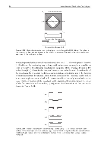
Figure 2.13 Illustration showing how vertical faces can be formed in {100} silicon. The edges of
the opening in the mask are aligned to the <100> orientation. The vertical face is etched at the
same rate as the horizontal surface.
producing useful anisotropically etched structures on {111} silicon is greater than on
{110} silicon. By combining dry etching with anisotropic etching it is possible to
form a variety of freestanding structures in the plane of the wafer; a trench is dry
etched into {111} silicon in the shape of the structure to be formed; the sidewalls of
the trench can be protected by, for example, oxidizing the silicon and if the bottom
of the trench is then dry etched a little further, the silicon thus exposed can be etched
in an anisotropic wet etch, which will remove the silicon laterally beneath the struc-
ture. The lower surface of the structure will be protected from the etchant by virtue
of the fact that it is a slow etching {111} plane. An illustration of this process is
shown in Figure 2.14.
(a)
(b)
(c)
(d)
(e)
Figure 2.14 Process sequence for wet anisotropic etching of {111} silicon: (a) a trench is dry
etched in the silicon; (b) silicon is oxidized; (c) a second trench is dry etched at the bottom of the
first trench; (d) resist is removed and silicon is etched in wet anisotropic etch; and (e) oxide is
removed.