
Page 52 - MEMS Mechanical Sensors
P. 52
3.2 Simulation and Design Tools 41
The model contains a user-defined submodel (displacement limit controller)
that has two inputs: the input acceleration acting on the sensing element and the dis-
placement of the proof mass. It models the nonlinear behavior of the sensing ele-
ment in case the proof mass touches the mechanical stoppers (i.e., the displacement
x exceeds a certain x ). In this case the velocity of the proof mass is reduced to zero,
max
hence Integrator1 in the figure is reset to zero until an acceleration in the direction
away from the limit stopper is detected.
Another feature of the model is that a nonzero initial displacement of the proof
mass can be set by x , which puts an initial condition on the second integrator. The
0
summing block at the input sums up all external and internal forces acting on the
proof mass.
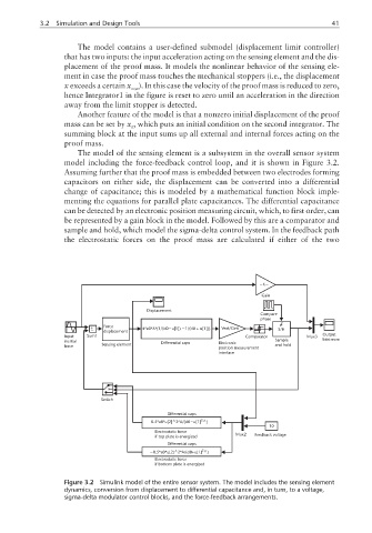
The model of the sensing element is a subsystem in the overall sensor system
model including the force-feedback control loop, and it is shown in Figure 3.2.
Assuming further that the proof mass is embedded between two electrodes forming
capacitors on either side, the displacement can be converted into a differential
change of capacitance; this is modeled by a mathematical function block imple-
menting the equations for parallel plate capacitances. The differential capacitance
can be detected by an electronic position measuring circuit, which, to first order, can
be represented by a gain block in the model. Followed by this are a comparator and
sample and hold, which model the sigma-delta control system. In the feedback path
the electrostatic forces on the proof mass are calculated if either of the two
−−
K
Gain
Displacement
Compare
phase
+ Force 4*e0*A*(1/(d0 u[1]) − 1/(d0 + u[1])) Vext/Cint
−
− displacement S/H
Input Sum1 Comparator Mux3 Output
inertial Differential caps Electronic Sample bitstream
force Sensing element and hold
position measurement
interface
Switch
Differential caps
∧
0.5*e0*u[2] 2*A/(d0 u[1] ∧ )
2
−
10
Electrostatic force
if top plate is energized Mux2 Feedback voltage
Differential caps
−0.5*e0*u[2] 2*A/(d0+u[1] ∧ )
∧
2
Electrostatic force
if bottom plate is energized
Figure 3.2 Simulink model of the entire sensor system. The model includes the sensing element
dynamics, conversion from displacement to differential capacitance and, in turn, to a voltage,
sigma-delta modulator control blocks, and the force-feedback arrangements.