
Page 81 - MEMS Mechanical Sensors
P. 81
70 Mechanical Sensor Packaging
liquid water forming at the interface [27]. These polymers, however, offer poor lev-
els of protection against alkaline solutions.
Protective silicon oxide and silicon nitride films possess a much greater resis-
tance to the diffusion of water molecules. These films can be applied both at wafer
level and on mounted chips using CVD processes. They must be free from cracks and
pinholes, and in the case of mounted chips, the films must be deposited on all the
exposed surfaces, including wirebonds and contact pads. The chemical resistance of
these films is fundamentally important since they will only be deposited in thick-
nesses of a few microns. Even very low corrosion rates (27 angstroms/day) will
remove a 1-micron-thick protective film after 1 year. Silicon carbide thin-films have
been found to offer the most promising levels of chemical resistance [28]. A further
consideration is the effects of thermal cycling, which can cause delamination of these
films due to TEC mismatches.
If the second order package is required to protect the device, the sealing
processes developed by the IC industry and described in Section 4.3.3 can be used. In
the case of MEMS packaging, second order capping can be further complicated by
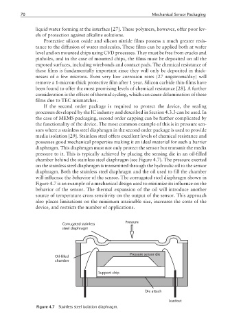
the functionality of the device. The most common example of this is in pressure sen-
sors where a stainless steel diaphragm in the second order package is used to provide
media isolation [29]. Stainless steel offers excellent levels of chemical resistance and
possesses good mechanical properties making it an ideal material for such a barrier
diaphragm. This diaphragm must not only protect the sensor but transmit the media
pressure to it. This is typically achieved by placing the sensing die in an oil-filled
chamber behind the stainless steel diaphragm (see Figure 4.7). The pressure exerted
on the stainless steel diaphragm is transmitted through the hydraulic oil to the sensor
diaphragm. Both the stainless steel diaphragm and the oil used to fill the chamber
will influence the behavior of the sensor. The corrugated steel diaphragm shown in
Figure 4.7 is an example of a mechanical design used to minimize its influence on the
behavior of the sensor. The thermal expansion of the oil will introduce another
source of temperature cross sensitivity on the output of the sensor. This approach
also places limitations on the minimum attainable size, increases the costs of the
device, and restricts the number of applications.
Pressure
Corrugated stainless
steel diaphragm
Pressure sensor die
Oil-filled
chamber
Support chip
Die attach
Leadout
Figure 4.7 Stainless steel isolation diaphragm.