
Page 420 -
P. 420
Single-Crystal Silicon Carbide MEMS: Fabrication, Characterization, and Reliability 7-9
Vin 1
R 2 R 3 R 4
I
R 1
R +∆R
R −∆R 1 4
1
Vo 1 Vo 2
R −∆R 1
3
R +∆R
2
Vin 1 Vo 1 Vin 2 Vo 2 Vin 1
I
V 40x 250 µm
Vin 2
(a) (b)
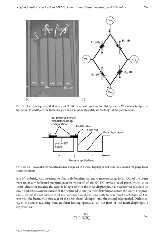
FIGURE 7.4 (a) Top view SEM picture of 6H-SiC beam with resistors and (b) equivalent Wheatstone bridge con-
figuration. R and R are the transverse piezoresistors while R and R are the longitudinal piezoresistors.
1 4 2 3
SiC piezoresistors in
Wheatstone bridge
configuration
Metallization
Push rod
Metal diaphragm
p-type SiC
beam
Pressure applied here
FIGURE 7.5 SiC cantilever beam transducer integrated to a metal diaphragm and push rod and used for gauge factor
characterization.
arm of the bridge was measured to obtain the longitudinal and transverse gauge factors. All of the beams
were uniaxially deformed perpendicular to within 4° of the 6H-SiC crystal’s basal plane, which is the
[0001] direction. Because the beam is integrated with the metal diaphragm, it is necessary to calculate the
strain and stresses on the surface of the beam and to analyze their distribution across the beam. The prob-
lem is solved as a superposition of two systems, namely: (1) one with an edge-fixed diaphragm, and (2)
one with the beam, with one edge of the beam fixed (clamped) and the second edge guided. Deflection,
w , at the center resulting from uniform loading (pressure) on the front of the metal diaphragm is
p
expressed as:
Pa 4
w (7.2)
p 64D
m
© 2006 by Taylor & Francis Group, LLC