
Page 163 - Machinery Component Maintenance
P. 163
146 Machinery Component Maintenance and Repair
Primary Causes of Flange Leakage
Several common causes of flange leakage are hereby outlined to create
an awareness of the effects of poor inspection procedure or materials:
Uneven Bolt Stress., Flanges bolted up unevenly cause some bolts to be
nearly loose while others are so heavily loaded that they locally crush the
gasket. This causes leaks, particularly in high-temperature service where
the heavily-loaded bolts tend to relax with subsequent loosening of the
joint.
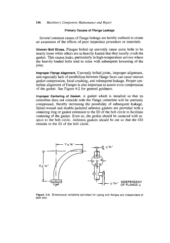
Improper Flange Alignment. Unevenly bolted joints, improper alignment,
and especially lack of parallelism between flange faces can cause uneven
gasket compression, local crushing, and subsequent leakage. Proper cen-
terline alignment of flanges is also important to assure even compression
of the gasket. See Figure 4-2 for general guidance.
Improper Centering of Gasket. A gasket which is installed so that its
centerline does not coincide with the flange centerline will be unevenly
compressed, thereby increasing the possibility of subsequent leakage.
Spiral-wound and double-jacketed asbestos gaskets are provided with a
centering ring or gasket extension to the ID of the bolt circle to facilitate
centering of the gasket. Even so, ,the gasket should be centered with re-
spcct to the bolt circlc. Asbestos gaskets should be cut so that the OD
extends to the ID of the bolt circle.
’I8 “
-* INDEPENDENT
’132
OF FLANGE 4
Figure 4-2. Dimensional variations permitted for piping and flanges are independent of
pipe size.