
Page 133 - Make Your Own PCBs with EAGLE from Schematic Designs to Finished Boards
P. 133
The routing grid specifies the grid to which the bend points in the tracks should be matched.
Reducing this number sometimes may be necessary to fit all the tracks in.
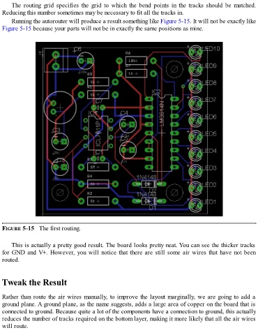
Running the autorouter will produce a result something like Figure 5-15. It will not be exactly like
Figure 5-15 because your parts will not be in exactly the same positions as mine.
FIGURE 5-15 The first routing.
This is actually a pretty good result. The board looks pretty neat. You can see the thicker tracks
for GND and V+. However, you will notice that there are still some air wires that have not been
routed.
Tweak the Result
Rather than route the air wires manually, to improve the layout marginally, we are going to add a
ground plane. A ground plane, as the name suggests, adds a large area of copper on the board that is
connected to ground. Because quite a lot of the components have a connection to ground, this actually
reduces the number of tracks required on the bottom layer, making it more likely that all the air wires
will route.