
Page 136 - Make Your Own PCBs with EAGLE from Schematic Designs to Finished Boards
P. 136
This time the autorouter failed to route just one air wire. Also, the ground plane has broken up.
There is a portion over on the right where the ground plane could not spread though because of the
design rules. Let’s try to sort out these problems.
If you cannot see where the air wire is, then it helps to temporarily hide some of the layers. The
air wires are all on the “19 Unrouted” layer.
The remaining air wire is between the two anodes of LED9 and LED10. All the positive leads of
the LEDs are connected together on the left. It would be easier if they were on the right because they
would then be on the same side as the connections from IC2. So let’s rip up all the tracks, rotate the
LEDs, and try again. Laying out a board is an iterative process. Unless you have a few components on
a large board, you are likely to have to make several attempts to route the board.
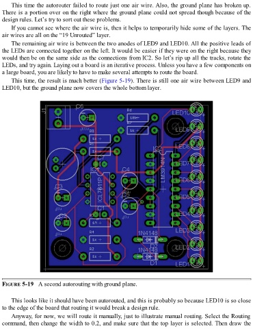
This time, the result is much better (Figure 5-19). There is still one air wire between LED9 and
LED10, but the ground plane now covers the whole bottom layer.
FIGURE 5-19 A second autorouting with ground plane.
This looks like it should have been autorouted, and this is probably so because LED10 is so close
to the edge of the board that routing it would break a design rule.
Anyway, for now, we will route it manually, just to illustrate manual routing. Select the Routing
command, then change the width to 0.2, and make sure that the top layer is selected. Then draw the