
Page 139 - Make Your Own PCBs with EAGLE from Schematic Designs to Finished Boards
P. 139
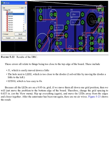
FIGURE 5-22   Results of the DRC.


      These errors all relate to things being too close to the top edge of the board. These include


        • J1, which is easily moved down a little
        • The hole next to LED2, which is too close to the diodes (I solved this by moving the diodes a

          little to the left.)
        • LED10, which is less easy to fix


      Because all the LEDs are on a 0.05-in. grid, if we move them all down one grid position, then we
  will just move the problem to the bottom edge of the board. Therefore, change the grid spacing to
  0.025 in. (on the View menu). Rip up everything (again), and move the LEDs away from the edges
  and closer together. After the autorouter has been run again, there are no air wires. Figure 5-23 shows
  the result.