
Page 215 - Make Your Own PCBs with EAGLE from Schematic Designs to Finished Boards
P. 215
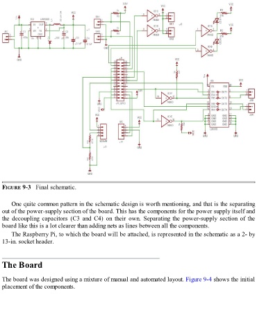
FIGURE 9-3   Final schematic.


      One quite common pattern in the schematic design is worth mentioning, and that is the separating
  out of the power-supply section of the board. This has the components for the power supply itself and
  the  decoupling  capacitors  (C3  and  C4)  on  their  own.  Separating  the  power-supply  section  of  the
  board like this is a lot clearer than adding nets as lines between all the components.

      The Raspberry Pi, to which the board will be attached, is represented in the schematic as a 2- by
  13-in. socket header.


  The Board


  The board was designed using a mixture of manual and automated layout. Figure 9-4 shows the initial
  placement of the components.