
Page 218 - Make Your Own PCBs with EAGLE from Schematic Designs to Finished Boards
P. 218
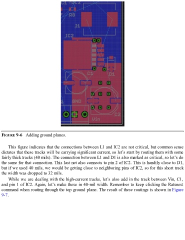
FIGURE 9-6   Adding ground planes.


      This figure indicates that the connections between L1 and IC2 are not critical, but common sense
  dictates that these tracks will be carrying significant current, so let’s start by routing them with some
  fairly thick tracks (40 mils). The connection between L1 and D1 is also marked as critical, so let’s do
  the same for that connection. This last net also connects to pin 2 of IC2. This is handily close to D1,
  but if we used 40 mils, we would be getting close to neighboring pins of IC2, so for this short track

  the width was dropped to 32 mils.
      While we are dealing with the high-current tracks, let’s also add in the track between Vin, C1,
  and pin 1 of IC2. Again, let’s make these in 40-mil width. Remember to keep clicking the Ratsnest

  command when routing through the top ground plane. The result of these routings is shown in Figure
  9-7.