
Page 222 - Make Your Own PCBs with EAGLE from Schematic Designs to Finished Boards
P. 222
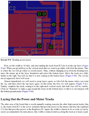
FIGURE 9-8   Routing across layers.


      First, set the width to 10 mils, and start making the track from IC2 pin 4 on the top layer (Figure

  9-8a). When you get halfway to the vertical track that we want to go under, left-click the mouse. This
  is where the via will go when we switch layers. Thus, without changing away from the Routing tool,
  move the mouse up to the layer dropdown and select the bottom layer. Move the track on a little
  further to the right. You will see that it is now routing on the bottom layer ( Figure 9-8b). The via has
  not yet appeared, but it will soon.

      Almost immediately we will need to swap layers again, so left-click the mouse where you want
  the via, and then select the top layer again. At this point, the first via will appear (Figure 9-8c).
  Finally, complete the track, routing it to the right-most vertical track, and both vias will be visible.
  Click on “Ratsnest” to make a gap around the track on the bottom layer so that it is not merged with
  the bottom ground plane (Figure 9-8d).


  Laying Out the Power and Motor Tracks


  The other area of the board that is worth manually routing concerns the other high-current tracks, that
  is, the tracks from IC3 to the screw terminals that provide power to the motors and also the regulated
  5-V line that provides power to the Raspberry Pi. Again, the width is chosen to be as wide as can be

  easily accommodated. In some places, this width is reduced midway along the track as it nears a pad.