
Page 219 - Make Your Own PCBs with EAGLE from Schematic Designs to Finished Boards
P. 219
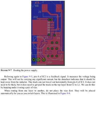
FIGURE 9-7   Routing the power supply.


      Referring again to Figure 9-5, pin 4 of IC2 is a feedback signal. It measures the voltage being
  output. This will not be carrying any significant current, but the datasheet indicates that it should be
  kept away from the inductor. This track can just travel out horizontally from pin 4 of IC2. It does not
  need to be thick, but it does need to get past the track on the top layer from C2 to L1. We can do this
  by hopping under it using a pair of vias.

      When  routing  from  one  layer  to  another,  do  not  place  the  vias  first.  They  will  be  placed
  automatically for you as you switch layers. This is illustrated in Figure 9-8.