
Page 216 - Make Your Own PCBs with EAGLE from Schematic Designs to Finished Boards
P. 216
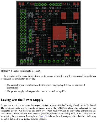
FIGURE 9-4   Initial component placement.


      In considering the board design, there are two areas where it is worth some manual layout before
  we unleash the autorouter. These are


        • The critical layout considerations for the power-supply chip IC2 and its associated
          components

        • The power supply and outputs of the motor controller chip IC3


  Laying Out the Power Supply


  As you can see, the power-supply components take almost a third of the right-hand side of the board.
  The  switched-mode  power  supply  is  based  around  the  LM2596S  chip.  The  datasheet  for  this
  integrated circuit (IC) indicates that there are certain paths between its associated components that
  need to be as short and low resistance as possible; otherwise, instability will result. There are also

  some fairly large currents flowing here. Figure 9-5 shows the relevant part of the datasheet indicating
  the paths that need to be kept as short as possible.