
Page 217 - Make Your Own PCBs with EAGLE from Schematic Designs to Finished Boards
P. 217
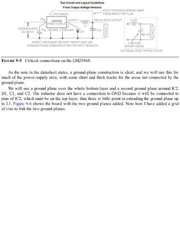
FIGURE 9-5   Critical connections on the LM2596S.


      As the note in the datasheet states, a ground-plane construction is ideal, and we will use this for
  much of the power-supply area, with some short and thick tracks for the areas not connected by the
  ground plane.

      We will use a ground plane over the whole bottom layer and a second ground plane around IC2
  D1, C1, and C2. The inductor does not have a connection to GND because it will be connected to
  pins of IC2, which must be on the top layer; thus there is little point in extending the ground plane up
  to L1. Figure 9-6 shows the board with the two ground planes added. Note how I have added a grid

  of vias to link the two ground planes.