
Page 240 - Make Your Own PCBs with EAGLE from Schematic Designs to Finished Boards
P. 240
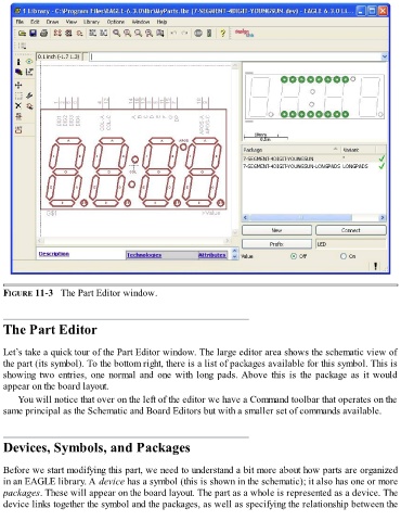
FIGURE 11-3   The Part Editor window.


  The Part Editor


  Let’s take a quick tour of the Part Editor window. The large editor area shows the schematic view of
  the part (its symbol). To the bottom right, there is a list of packages available for this symbol. This is
  showing  two  entries,  one  normal  and  one  with  long  pads. Above  this  is  the  package  as  it  would

  appear on the board layout.
      You will notice that over on the left of the editor we have a Command toolbar that operates on the
  same principal as the Schematic and Board Editors but with a smaller set of commands available.


  Devices, Symbols, and Packages


  Before we start modifying this part, we need to understand a bit more about how parts are organized
  in an EAGLE library. A device has a symbol (this is shown in the schematic); it also has one or more
  packages. These will appear on the board layout. The part as a whole is represented as a device. The
  device links together the symbol and the packages, as well as specifying the relationship between the