
Page 249 - Make Your Own PCBs with EAGLE from Schematic Designs to Finished Boards
P. 249
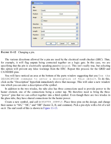
FIGURE 11-12   Changing a pin.


      The various directions allowed for a pin are used by the electrical result checker (ERC). Thus,
  for  example,  it  will  flag  outputs  being  connected  together  on  a  logic  gate.  In  this  case,  we  are
  specifying that the pin is electrically speaking passive (pass). This isn’t really true, but selecting

  this option will prevent any false warnings from the ERC. Repeat this process for the GRID and
  CATHODE pins.

      You will have noticed an area at the bottom of the parts window suggesting that you Use the
  DESCRIPTION command to enter a description of this object. To do this,
  click on the “Description” hyperlink immediately above that message. This will enter a new window
  into which you can enter a description of the symbol.
      In addition to the two triodes, the tube also has three connections used to provide power to the
  heater  element,  one  of  the  connections  being  a  center  tap.  We  therefore  need  to  bring  the  three

  “power” pins that we can collect together into a third symbol. Even though there are two triodes in
  the glass tube, they have shared connections for the heater power.
      Create a new symbol, and call it HEATER_SUPPLY. Place three pins on the design, and change

  their names to “HA,” “HC,” and “HB” (heater A, B, and common). Pick a pin style with a bit of a tail
  on it. The end result of this is shown in Figure 11-13.