
Page 52 - Make Your Own PCBs with EAGLE from Schematic Designs to Finished Boards
P. 52
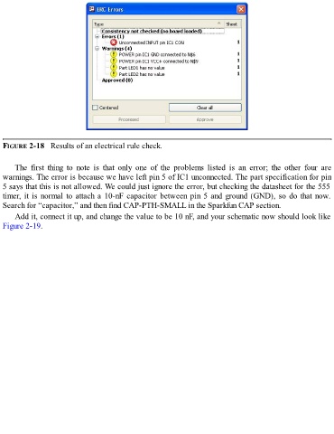
FIGURE 2-18   Results of an electrical rule check.


      The  first  thing  to  note  is  that  only  one  of  the  problems  listed  is  an  error;  the  other  four  are
  warnings. The error is because we have left pin 5 of IC1 unconnected. The part specification for pin
  5 says that this is not allowed. We could just ignore the error, but checking the datasheet for the 555
  timer, it is normal to attach a 10-nF capacitor between pin 5 and ground (GND), so do that now.
  Search for “capacitor,” and then find CAP-PTH-SMALL in the Sparkfun CAP section.

      Add it, connect it up, and change the value to be 10 nF, and your schematic now should look like
  Figure 2-19.