
Page 53 - Make Your Own PCBs with EAGLE from Schematic Designs to Finished Boards
P. 53
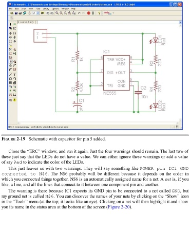
FIGURE 2-19   Schematic with capacitor for pin 5 added.


      Close the “ERC” window, and run it again. Just the four warnings should remain. The last two of
  these just say that the LEDs do not have a value. We can either ignore these warnings or add a value
  of say Red to indicate the color of the LEDs.

      This just leaves us with two warnings. They will say something like POWER pin IC1 GND
  connected to N$6.  The  N$6  probably  will  be  different  because  it  depends  on  the  order  in
  which you connected things together. N$6 is an automatically assigned name for a net. A net is, if you
  like, a line, and all the lines that connect to it between one component pin and another.

      The warning is there because IC1 expects its GND pin to be connected to a net called GND, but
  my ground net is called N$6. You can discover the names of your nets by clicking on the “Show” icon
  in the “Tools” menu (at the top; it looks like an eye). Clicking on a net will then highlight it and show
  you its name in the status area at the bottom of the screen (Figure 2-20).