
Page 285 - Manufacturing Engineering and Technology - Kalpakjian, Serope : Schmid, Steven R.
P. 285
264 Chapter 11 Metal-Casting Processes and Equipment
S\ 7. Vents, which are placed in molds to carry off gases produced
Cope side
when the molten metal comes into contact with the sand in the
Plate mold and the core. Vents also exhaust air from the mold cavity
as the molten metal flows into the mold.
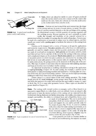
Patterns. Patterns are used to mold the sand mixture into the shape
Drag side of the casting and may be made of wood, plastic, or metal. The selec-
tion of a pattern material depends on the size and shape of the casting,
FIGURE ll.4 A typical metal match-plate the dimensional accuracy and the quantity of castings required, and
pattern used in sand casting. the molding process. Because patterns are used repeatedly to make
molds, the strength and durability of the material selected for a
pattern must reflect the number of castings that the mold will produce. Patterns may
be made of a combination of materials to reduce wear in critical regions, and they
usually are coated with a parting agent to facilitate the removal of the casting from
the molds.
Patterns can be designed with a variety of features to fit specific applications
and economic requirements. One-piece patterns, also called loose or solid patterns,
generally are used for simpler shapes and low~quantity production; they generally
are made of wood and are inexpensive. Split patterns are two-piece patterns, made
such that each part forms a portion of the cavity for the casting; in this way, castings
with complicated shapes can be produced. Match-plate patterns are a common type
of mounted pattern in which two-piece patterns are constructed by securing each
half of one or more split patterns to the opposite sides of a single plate (Fig. 11.4).
In such constructions, the gating system can be mounted on the drag side of the pat-
tern. This type of pattern is used most often in conjunction with molding machines
and large production runs to produce smaller castings.
An important development in molding and pattern making is the application
of rapid prototyping (Chapter 20). In sand casting, for example, a pattern can be
fabricated in a rapid-prototyping machine and fastened to a backing plate at a frac-
tion of the time and cost of machining a pattern. There are several rapid prototyping
techniques with which these tools can be produced quickly.
Pattern design is a critical aspect of the total casting operation. The design
should provide for metal shrinkage, permit proper metal flow in the mold cavity,
and allow the pattern to be easily removed from the sand mold by means of a taper
or draft (Fig. 11.5 ) or some other geometric feature. (These topics are described in
greater detail in Chapter 12.)
Damage
Cores.
For castings with internal cavities or passages, such as those found in an
automotive engine block or a valve body, cores are utilized. Cores are placed in the
mold cavity to form the interior surfaces of the casting and are removed from the
finished part during shakeout and further processing. Like molds, cores must possess
strength, permeability, the ability to withstand heat, and collapsibility; hence, cores
are made of sand aggregates. The core is anchored by
core prints, which are recesses added to the pattern to
locate and support the core and to provide vents for
Pattern T( (47 Draft angle the escape of gases (Fig. 11.6a). A common problem
»`,s, Flask with cores is that (for some casting requirements, as in
. ...,. " lf Sand mold the case where a recess is required) they may lack suf-
ficient structural support in the cavity. To keep the
Good
Poor ' ...,.,, i ‘ core from shifting, metal supports (chaplets) may be
used to anchor the core in place (Fig. 11.6b).
FIGURE I l.5 Taper on patterns for ease of removal from the Cores generally are made in a manner similar to
sand mold. that used in sand moldmaking; the majority are made