
Page 288 - Manufacturing Engineering and Technology - Kalpakjian, Serope : Schmid, Steven R.
P. 288
f __ S 26
Expendable-mold, Permanent-pattern Casting Processes
Section 11.2
HWS Q
Core prints
Core prints
AVV: ,,5,
%
Gate
Mechanical drawing of part Cope pattern plate Drag pattern plate Core boxes
"
(H) (D) (C) (d)
/ee
2
Sprue si. Z/
,-
4
*%
»
\-
§' Flask ~ 'vlt " Cope after ramming “V ,,i,
r§§§fi?:¥¥#
"W
with sand and
Core halves removing perrern, Drag ready Drag after
pasted together Cope ready for sand sprue’ and risers for sand removing pattern
(G) (f) (Q) (li) (I)
\\\T”f \
pins
7 fr""“ 1
Drag with core Cope and drag assembled Casting as removed Casting ready
set in place and ready for pouring from mold; heat treated for shipment
(i) (K) (l)
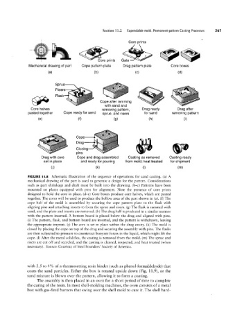
FIGURE ||.8 Schematic illustration of the sequence of operations for sand casting. (a) A
mechanical drawing of the part is used to generate a design for the pattern. Considerations
such as part shrinkage and draft must be built into the drawing. (b-c) Patterns have been
mounted on plates equipped with pins for alignment. Note the presence of core prints
designed to hold the core in place. (d-e) Core boxes produce core halves, which are pasted
together. The cores will be used to produce the hollow area of the part shown in (a). (f) The
cope half of the mold is assembled by securing the cope pattern plate to the flask with
aligning pins and attaching inserts to form the sprue and risers. (g) The flask is rammed with
sand, and the plate and inserts are removed. (h) The drag half is produced in a similar manner
with the pattern inserted. A bottom board is placed below the drag and aligned with pins.
(i) The pattern, flask, and bottom board are inverted, and the pattern is withdrawn, leaving
the appropriate imprint. (j) The core is set in place within the drag cavity. (k) The mold is
closed by placing the cope on top of the drag and securing the assembly with pins. The flasks
are then subjected to pressure to counteract buoyant forces in the liquid, which might lift the
cope. (l) After the metal solidifies, the casting is removed from the mold. (m) The sprue and
risers are cut off and recycled, and the casting is cleaned, inspected, and heat treated (when
necessary). Source: Courtesy of Steel Founders’ Society of America.
with 2.5 to 4% of a thermosetting resin binder (such as phenol-formaldehyde) that
coats the sand particles. Either the box is rotated upside down (Fig. 11.9), or the
sand mixture is blown over the pattern, allowing it to form a coating.
The assembly is then placed in an oven for a short period of time to complete
the curing of the resin. In most shell-molding machines, the oven consists of a metal
box with gas-fired burners that swing over the shell mold to cure it. The shell hard-