
Page 238 - Mastering SolidWorks
P. 238
|
tutorial: controllinG PictureS, teXt, colorS, anD StYleS 209
2. Insert a sketch picture in this sketch. Use Sketch Picture 1.tif from the download
material for Chapter 6. Use Tools ➢ Sketch Tools ➢ Sketch Picture.
3. Resize and reposition the image so the endpoints of the construction line are near the
centers of the holes on the ends of the part. To move the image, just double-click it first
and then drag it. To resize it, drag the corners—or use the Scale tool in the Sketch Picture
PropertyManager if you prefer.
4. In the Transparency panel of the Sketch Picture PropertyManager, select the User Defined
option, select the Eyedropper tool, and then click in the white background of the image.
Make sure that the color field next to the Eyedropper tool changes to white.
5. Slide the Transparency and Matching Tolerance sliders all the way to the right, or type
1.00 in the number boxes.
6. Close the sketch and rename it Sketch Image Front View.
7. Insert the image Sketch Picture 2.tif, also from the website download, in a sketch on
the right plane, and resize it to fit with the first image. Center it symmetrically about the
origin. Also, set the transparency to the same setting as the first image.
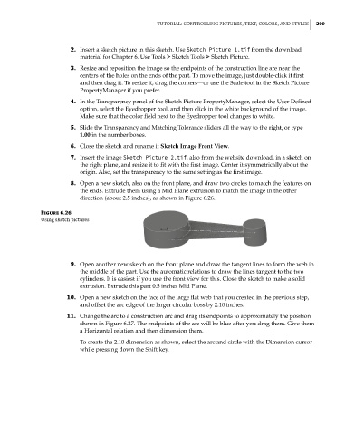
8. Open a new sketch, also on the front plane, and draw two circles to match the features on
the ends. Extrude them using a Mid Plane extrusion to match the image in the other
direction (about 2.5 inches), as shown in Figure 6.26.
Figure 6.26
using sketch pictures
9. Open another new sketch on the front plane and draw the tangent lines to form the web in
the middle of the part. Use the automatic relations to draw the lines tangent to the two
cylinders. It is easiest if you use the front view for this. Close the sketch to make a solid
extrusion. Extrude this part 0.5 inches Mid Plane.
10. Open a new sketch on the face of the large flat web that you created in the previous step,
and offset the arc edge of the larger circular boss by 2.10 inches.
11. Change the arc to a construction arc and drag its endpoints to approximately the position
shown in Figure 6.27. The endpoints of the arc will be blue after you drag them. Give them
a Horizontal relation and then dimension them.
To create the 2.10 dimension as shown, select the arc and circle with the Dimension cursor
while pressing down the Shift key.