Page 279 - Mathematical Models and Algorithms for Power System Optimization
P. 279

Optimization Method for Load Frequency Feed Forward Control 271
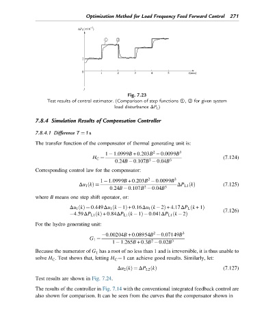


                                                     Fig. 7.23
                    Test results of central estimator. (Comparison of step functions ①, ② for given system
                                               load disturbance ΔP L )

               7.8.4 Simulation Results of Compensation Controller

               7.8.4.1 Difference T ¼1s

               The transfer function of the compensator of thermal generating unit is:
                                                               2
                                            1 1:0999B +0:203B  0:0099B    3
                                       H C ¼                                               (7.124)
                                                             3
                                                0:24B 0:107B  0:04B   3
               Corresponding control law for the compensator:
                                                             2
                                          1 1:0999B +0:203B  0:0099B    3
                                 Δu 1 kðÞ ¼                              ΔP L1 kðÞ         (7.125)
                                                           2
                                              0:24B 0:107B  0:04B   3
               where B means one step shift operator, or:
                                                                              ð
                                                              ð
                             Δu 1 kðÞ ¼ 0:449Δu 1 k  1ð  Þ +0:16Δu 1 k  2Þ +4:17ΔP L k +1Þ
                                                                                           (7.126)
                                                                       ð
                              4:59ΔP L1 kðÞ +0:84ΔP L1 k  1ð  Þ 0:041ΔP L1 k  2Þ
               For the hydro generating unit:
                                                               2
                                           0:00204B +0:08954B  0:07149B    3
                                     G 1 ¼
                                                              2
                                               1 1:265B +0:3B  0:02B   3
               Because the numerator of G 1 has a root of no less than 1 and is irreversible, it is thus unable to
               solve H C . Test shows that, letting H C ¼1 can achieve good results. Similarly, let:

                                                 Δu 2 kðÞ ¼ ΔP L2 kðÞ                      (7.127)
               Test results are shown in Fig. 7.24.
               The results of the controller in Fig. 7.14 with the conventional integrated feedback control are
               also shown for comparison. It can be seen from the curves that the compensator shown in
   274   275   276   277   278   279   280   281   282   283   284