
Page 280 - Mathematical Models and Algorithms for Power System Optimization
P. 280
272 Chapter 7
(A) (B)
(C) (D)
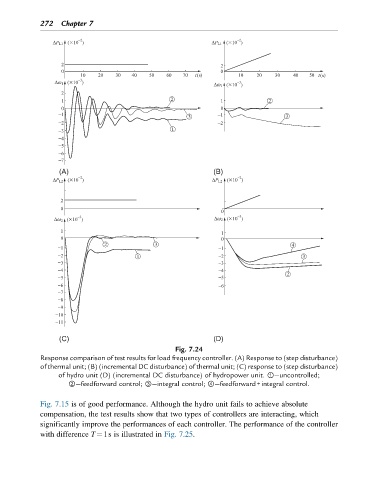
Fig. 7.24
Response comparison of test results for load frequency controller. (A) Response to (step disturbance)
of thermal unit; (B) (incremental DC disturbance) of thermal unit; (C) response to (step disturbance)
of hydro unit (D) (incremental DC disturbance) of hydropower unit. ①—uncontrolled;
②—feedforward control; ③—integral control; ④—feedforward+integral control.
Fig. 7.15 is of good performance. Although the hydro unit fails to achieve absolute
compensation, the test results show that two types of controllers are interacting, which
significantly improve the performances of each controller. The performance of the controller
with difference T¼1s is illustrated in Fig. 7.25.