
Page 276 - Mathematical Models and Algorithms for Power System Optimization
P. 276
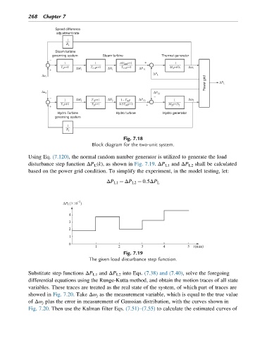
268 Chapter 7

                       Speed difference
                       adjustment rate


                       Steam turbine
                      governing system   Steam turbine           Thermal generator


                                                                                  Power grid


                        Hydro Turbine          Hydro turbine     Hydro generator
                       governing system


                                                  Fig. 7.18
                                     Block diagram for the two-unit system.
            Using Eq. (7.120), the normal random number generator is utilized to generate the load
            disturbance step function ΔP L (k), as shown in Fig. 7.19. ΔP L1 and ΔP L2 shall be calculated
            based on the power grid condition. To simplify the experiment, in the model testing, let:

                                           ΔP L1 ¼ ΔP L2 ¼ 0:5ΔP L


                                                  Fig. 7.19
                                    The given load disturbance step function.

            Substitute step functions ΔP L1 and ΔP L2 into Eqs. (7.38) and (7.40), solve the foregoing
            differential equations using the Runge-Kutta method, and obtain the motion traces of all state
            variables. These traces are treated as the real state of the system, of which part of traces are
            showed in Fig. 7.20. Take Δω j as the measurement variable, which is equal to the true value
            of Δω j plus the error in measurement of Gaussian distribution, with the curves shown in
            Fig. 7.20. Then use the Kalman filter Eqs. (7.51)–(7.55) to calculate the estimated curves of